*Please prepare a license ID and password for the license administrator.
*It is different from the service for JMAG WEB MEMBER (free membership). Please be careful.
Overview

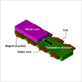
Linear motors are widely used for carrier devices and machine tools because of their high-speed performance, high acceleration and deceleration, and accurate positioning. A type of linear motor called a permanent magnet linear motor has harmonic components such as cogging and ripples in its thrust because of its structure and how it operates. These components have a large influence on velocity control and positioning accuracy. The thing that separates linear motors from rotating motors is that linear motors have edges, limiting how far they can move. This is why linear motors have different characteristics when the mover is positioned in the center of the stator and when it is at the edge. In order to create a more advanced control design, it is possible to use a control simulation to obtain a linear motor model that exhibits more detailed behavior that is based on an actual machine.
With JMAG, it is possible to create a linear motor model that is detailed and conforms to a real machine, and that accounts for spatial harmonics and magnetic saturation characteristics included in a permanent magnet linear motor. Importing this linear motor model, a “JMAG-RT model,” to a circuit/control simulator makes it possible to run a linked simulation that accounts for the linear motor’s magnetic saturation characteristics and spatial harmonics as well as the driver’s control characteristics.
This Application Note presents how to use the JMAG-RT to obtain the space harmonics and current dependency of the thrust and coil inductance and import them to a circuit/control simulator as a JMAG-RT model. From there, it shows how to perform an analysis that controls the position of the permanent magnet linear motor to the desired value.
Response characteristic/Thrust Variation
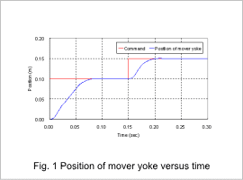
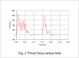
Fig. 1 shows the mover position versus time, and fig. 2 shows the thrust force versus time. Fig. 1 shows the time taken for the mover to reach the command value. The JMAG-RT model accounts for the motor geometry, so the thrust varies according to the positional relationship between the mover and the slots.


