
Circuit / Control
- Sort condition
- Newest first
- Oldest first
- Large number of views
-
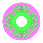
[RTML-060] IM Constant rating 100(kW)
Type: IM | Max Power: 100(kW) | Stator(Outside Diameter): 200(mm) | Height: 65(mm) | Voltage/Current: DC500(V)/600(A) | Rotor/Mover: Cage
-
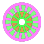
[RTML-052] WFSM_04
Type: WFSM | Max Power: 10(kW) | Stator(Outside Diameter): 185(mm) | Height: 40(mm) | Voltage/Current: DC240(V)/84.8(A), DC300(V)/50(A) | Rotor/Mover: WF | Number of Phases: 3
-
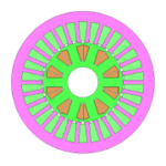
[RTML-053] WFSM_05
Type: WFSM | Max Power: 10(kW) | Stator(Outside Diameter): 185(mm) | Height: 50(mm) | Voltage/Current: DC240(V)/84.8(A), DC300(V)/35(A) | Rotor/Mover: WF | Number of Phases: 3
-
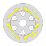
[RTML-054] WFSM_06
Type: WFSM | Max Power: 75(kW) | Stator(Outside Diameter): 212(mm) | Height: 200(mm) | Voltage/Current: DC600(V)/250(A), DC200(V)/20(A) | Rotor/Mover: WF | Number of Phases: 3
-
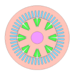
[RTML-055] WFSM_07
Type: WFSM | Max Power: 75(kW) | Stator(Outside Diameter): 212(mm) | Height: 200(mm) | Voltage/Current: DC600(V)/250(A), DC600(V)/45(A) | Rotor/Mover: WF | Number of Phases: 3
-
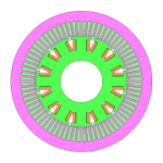
[RTML-056] WFSM_08
Type: WFSM | Max Power: 75(kW) | Stator(Outside Diameter): 400(mm) | Height: 65(mm) | Voltage/Current: DC500(V)/283(A), DC600(V)/50(A) | Rotor/Mover: WF | Number of Phases: 3
-
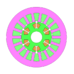
[RTML-051] WFSM_03
Type: WFSM | Max Power: 10(kW) | Stator(Outside Diameter): 115(mm) | Height: 150(mm) | Voltage/Current: DC240(V)/84.8(A), DC300(V)/15(A) | Rotor/Mover: WF | Number of Phases: 3
-

[L-MB-30] Accurately Identifying Motor Characteristics During Control with JMAG-RT
In general, the characteristics of motor models used in control circuit simulation of a motor drive system are often assumed to be constant when the motor is in drive mode.
-
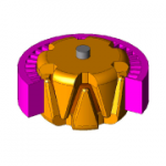
[JAC216] Simulation of a Claw-Pole Type Alternator Using a Control Simulator and JMAG-RT
In this example, the output voltage and field current of a claw-pole type alternator is checked when the rotor speed is changed.
-
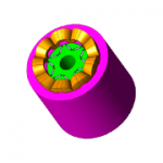
[JAC214] Monitoring the Radial Force Acting on the Teeth of IPM Motors Using Circuit Control Simulation
In this example, an IPM motor as a JMAG-RT model is captured in a control/circuit simulator, and radial forces acting on the teeth during motor driving is monitored while changing…
-
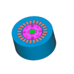
[JAC037] Vector Control Analysis of an IPM Motor Using Control Simulator and the JMAG-RT
The purpose of this Application Note is to demonstrate how to import a JMAG-RT model to a control/circuit simulator after using the JMAG-RT to obtain the inductance spatial harmon…
-
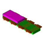
[JAC134] Speed Control Analysis of a Permanent Magnet Linear Motor Using the Control Simulator and the JMAG-RT
This Application Note presents how to use JMAG-RT to obtain the spatial harmonics and current dependency of the thrust and coil inductance, and import them to a circuit/control si…
-
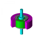
[JAC291] Control Simulation of Switching Number of Poles in a 6-Phase Induction Machine
In this document, the behavior of a 6-phase induction motor during the switching of the number of poles is evaluated by simulation.
-
[JAC215] Simulation of an IPM Motor with a Delta Connection Using a Control Simulator and JMAG-RT
In this example, a JMAG-RT model is incorporated into a control/circuit simulator to monitor the circulating current when an IPM motor is being driven.
-
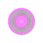
[JAC227] Circuit Control Simulation for Three-Phase Induction Motor
In this example, we conduct a circuit simulation to control current and speed by incorporating the JMAG-RT model of an induction motor into the control/circuit simulator.
-
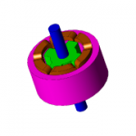
[JAC162] Drive Simulation of an SR Motor using a Control Simulator and JMAG-RT
In this Application Note, after using JMAG-RT to obtain an SR motor’s torque and inductance characteristics, the JMAG-RT model is imported into a circuit/control simulator, voltag…