Contents
1. Background
2. Loss modeling in the JMAG-RT PMSM model
3. Loss modeling in the JMAG-RT induction machine model
4. Future challenges
5. References
1. Background
A highly accurate plant model is required for motor drive simulation for model-based design. JMAG-RT can generate highly accurate plant models from FEA models. The JMAG-RT models can model the effects of machine constants with magnetic saturation and dependencies on mechanical angle. It is also possible to retain iron loss as data and evaluate driving loss.
In this paper, we explain how loss is modeled in a JMAG-RT model.
2. Loss modeling in the JMAG-RT PMSM model
The loss is roughly divided into copper loss, iron loss, stray loss, and mechanical loss. Of these, JMAG-RT can model copper loss and iron loss. Copper loss is calculated from coil resistance and current values. Iron loss is calculated using FEA when generating a JMAG model. A JMAG-RT model, especially PMSM, does not consider transient eddy current loss (magnet eddy current loss, etc.) because it obtains machine constants for each current amplitude, phase, and mechanical angle.
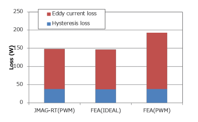
The iron loss of the PMSM model can be made to depend on the current amplitude, phase, and rotation speed using FEA. 3-phase AC is modeled when generating a JMAG-RT model. Therefore, iron loss information for a JMAG-RT model includes iron loss components caused from fundamental waves and spatial harmonics but does not include time harmonic components. Fig. 1 shows the iron loss in the JMAG-RT PMSM model during PWM driving. Comparisons were made with results (FEA (PWM)) obtained by applying a current waveform during PWM driving, obtained by motor drive simulation, into an FEA model and calculating iron loss. When harmonic currents are applied to the FEA model, loss is increased because harmonic iron loss is taken into account. On the other hand, the JMAG-RT model shows the same values as when an ideal sinusoidal current waveform is applied to the FEA model.

Fig. 1 Iron loss of JMAG-RT PMSM model during PWM driving
8-pole, 48-slot IPM motor PWM driving loss. The evaluation operating point is 1,200 rpm, the current amplitude is 250 A, the current phase is 0 degree, and the carrier frequency is 6 kHz. For FEA (IDEAL) the results were obtained from applying a sinusoidal current waveform, and for FEA (PWM) the iron loss was computed using the current waveform obtained by motor drive simulation. It can be seen that the eddy current loss increases due to the influence of harmonics.

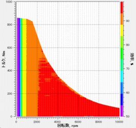
Fig. 4 Induction machine efficiency map
The T-type equivalent circuit is used when generating an induction machine efficiency map. Therefore, it is possible to evaluate loss that includes no-load iron loss and stray load iron loss.
You need to sign in as a Regular JMAG Software User (paid user) or JMAG WEB MEMBER (free membership).
By registering as a JMAG WEB MEMBER, you can browse technical materials and other member-only contents for free.
If you are not registered, click the “Create an Account” button.
Create an Account Sign in


