Overview
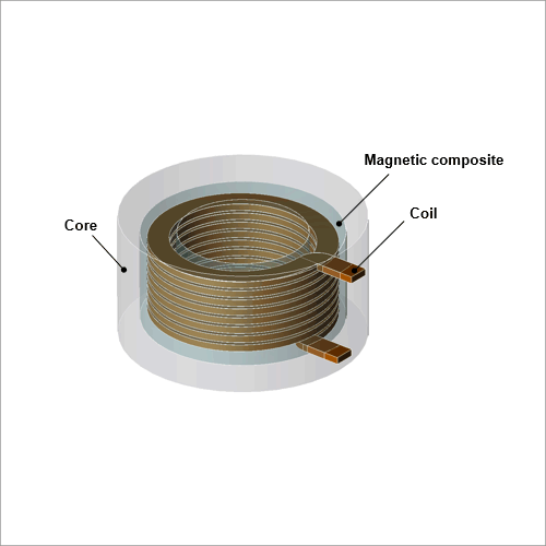
Equivalent circuit analyses are effective for obtaining the impedance frequency characteristics of chopper inductors. Comprehensive equivalent circuits can more precisely reproduce the actual phenomenon. This approach also helps engineers grasp the resonant phenomenon of inductors that operate in high-frequency regions.
In this example, a spiral chopper inductor to obtain the frequency characteristics of the impedance.
Analysis Results
This section describes the impedance characteristics.
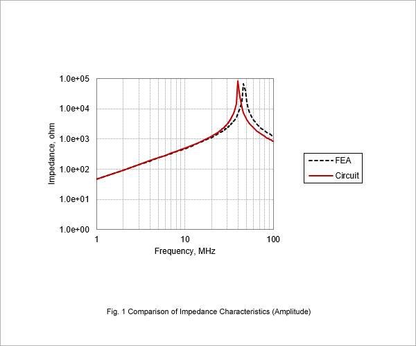
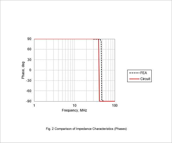
Fig. 1 compares the magnitude of the impedance obtained by FEA and the equivalent circuit. Fig. 2 compares the phases.
The impedance characteristics obtained using the equivalent circuit in Fig. 1 and 2 reproduce the FEA results that include the resonance phenomenon. The impedance characteristics obtained by the equivalent circuit does have some error in the resonance, but a more comprehensive equivalent circuit should obtain results that better approximate the real phenomenon.
Equivalent Circuit
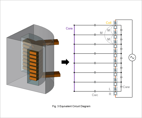
Fig. 3 provides a diagram of the equivalent circuit. The geometric shapes of the model and physical phenomena are converted into equivalent circuits on a one-to-one basis. The equivalent circuits are calculated using MATLAB/Simulink. The circuit constants of the equivalent circuits are obtained using JMAG-Designer as follows:
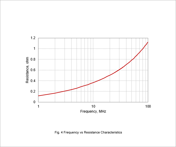
The winding resistance analysis to run a frequency analysis that takes into account the frequency dependency of the skin and proximity effects to obtain the winding resistance. The model geometry and field symmetry make an axial symmetric frequency analysis suitable for this analysis. Fig. 4 outlines the resistance characteristics obtained by the analysis.
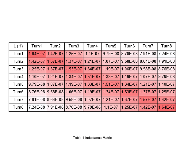
The skin and proximity effects do influence the winding inductance, but the effects are small enough to ignore. Therefore, the winding inductance calculation only uses the results obtained by a single frequency analysis. This case study runs an analysis for 1 MHz. The analysis isolates and obtains the self-inductance and mutual inductance because each wire affects the other wire characteristics. The model geometry and field symmetry make an axial symmetric frequency analysis suitable for this analysis. Table 1 provides the inductance matrix obtained by the analysis. Coupling coefficients express the mutual inductance for the circuit.
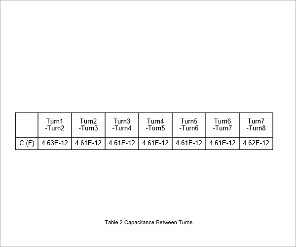
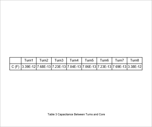
A static electric field analysis obtains capacitance because the part capacitance can be obtained from the surface charge produced by the electric potential between those parts. The analysis requires a full model because the positional relationship of the parts influences the capacitance. Although the coil is one long wire, the model needs to have ring geometry for each turn to obtain the capacitance between turns. Table 2 and Table 3 present the capacitance obtained by the analysis.