Overview

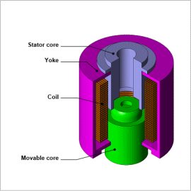
JMAG enables you to create a detailed and actual-machine faithful solenoid valve model that accounts for attraction force contained in a solenoid valve, inductance harmonic, or current dependency. A link simulation that accounts for both the solenoid valve magnetic saturation, or spatial harmonic and the control characteristics of the motor drive can be run by importing this solenoid valve model “JMAG-RT model” in a circuit/control simulator.
This note presents how JMAG-RT can be used to calculate attraction forces and coil inductance that varies with harmonic and current. The result is the JMAG-RT model used as a reference for a circuit / control simulator that runs a transient analysis to run an analysis that controls the solenoid valve position within the desired Value.
The position of the movable core and the excitation current versus time
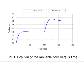
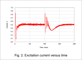
The position of the movable core versus time is indicated in Fig. 1, and the excitation current versus time is indicated in Fig. 2. The position of the movable core is moved from 0 mm to 1.5 mm, and then moved from 1.5 mm to 3.0 mm, as indicated in Fig. 1. Even though the movable core moves 1.5 meters in both instances, the movement tracks of the core differ due to the electromagnetic force and inductance that are affected by the current and position, and also the spring constant. A surge occurs the moment the movable core begins moving, as indicated in Fig. 2. This surge should be investigated further if it is fairly large, because electrical equipment near the surge could be damaged.


