Magnetic Component
A shift toward higher frequencies and more compact power electronic systems made possible by SiC, GaN, and other power devices has significantly changed magnetic component design for those systems. However, higher frequencies and miniaturization intensify skin and proximity effects as well as stray capacitance between turns, which complicates the impedance characteristics of magnetic components. Higher losses resulting in higher temperatures also necessitate more comprehensive designs. Engineers can actively use simulation to precisely capture this broad range of phenomena to substantially improve performance and development efficiency.
JMAG simulation technology can incorporate displacement currents to seamlessly cover wideband analysis the low-frequencies often used in FEA up to the high-frequency domain. These analyses elevate the level of magnetic component design by not only accurately obtaining impedance and other characteristics but also accounting for nonlinear material properties, the skin effect caused by eddy currents, stray capacitance, and other such phenomena.
Full-Wave FEA
JMAG enables frequency analyses that account for displacement current and magnetic field analyses that accurately incorporate electromagnetic propagation influenced by dielectric properties and dimesons of materials as well as dimensional resonance.
Resonance Phenomena Captured by Full-Wave FEA
Analyses can precisely simulate the phenomena essential to grasp the impedance characteristics.
| Resonance Phenomena | Full-Wave FEA Process | |
|---|---|---|
| Resonance inherent to magnetic materials | Natural resonance |
|
| Dimensional resonance |
|
|
| Self-resonance | Entire machine structure acting as a lumped LC resonant circuit |
|
| A portion of the machine structure acting as a localized LC resonant circuit (multiple resonance) |
||
Capturing and evaluating circuit constants, multiple resonance circuits arising from stray capacitance, and other physical phenomena through FEA results provides the insight necessary to enhance designs. High-speed JMAG solvers facilitate analysis of high-fidelity three-dimensional models that can simulate each wire strand.
Evaluation items
Inductance, stray capacitance, impedance characteristics, Q value, high-frequency resistance, coupling coefficient, resonant circuit, efficiency, displacement current, induced voltage, load current, power, copper loss, iron loss, stray load loss, temperature distribution, capacitance, electric field intensity, sound pressure, and magnetostriction
Use Case
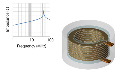
Impedance Characteristic Evaluation of Boost Chopper Inductors
This case study obtains the impedance characteristics of a step-upboost chopper inductor in a DC-DC converter with a laminated winding and one with a spiral winding. Full-Wave FEA can accurately capture the stray capacitance between turns to evaluate the different resonant frequencies in each inductor.
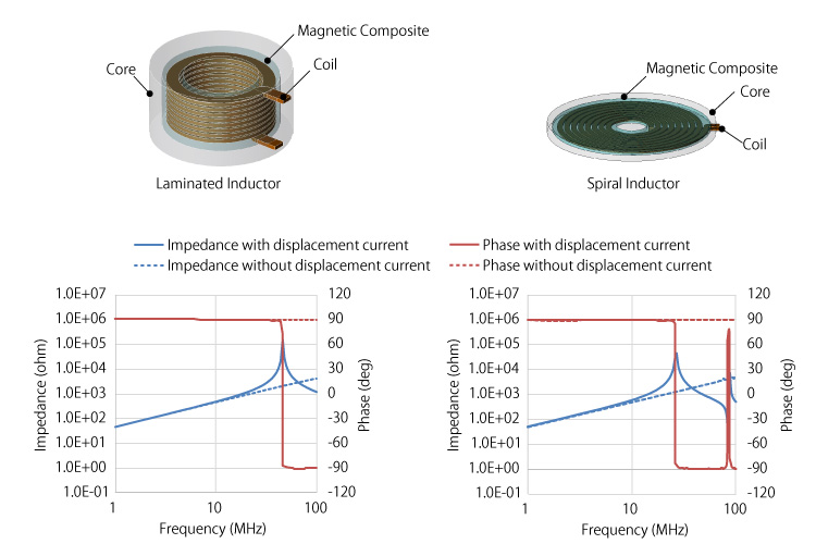
Impedance Characteristics of a Laminated/Spiral Inductor
The results above present the impedance of a laminated inductor (left) and a spiral inductor (right). Analyses accounting for the displacement current successfully simulate the resonant phenomena and obtain results indicating resonance at 46 MHz in the laminated inductor and 27 MHz in the spiral inductor.
JMAG features
Magnetic field frequency analysis, high-speed solver, skin effect, eddy current loss, electrical field distribution, complex permeability, and complex permittivity
Leaflet

This case study examines the frequency characteristics of impedance in a chopper inductor with a laminated winding structure and one with a spiral win...
Impedance Characteristic Evaluation of a Transformer in a Resonant LLC Converter
Transformers crucial to resonant LLC converter performance significantly influence the resonance characteristics. Miniaturization and a shift to higher frequencies increase leakage flux, which in turn reduces the coupling coefficient and drives up losses. Simulations to precisely evaluate the magnetic flux paths in converters, especially at high frequencies, are essential. JMAG takes advantage of Full-Wave FEA that accounts for stray capacitance to evaluate wideband impedance characteristics.
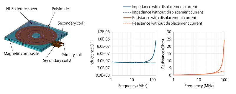
Inductance and Resistance with Open Secondary Coils (Left: Inductance; Right: Resistance)
The analysis accounting for displacement current indicates a spike in inductance and resistance around 30 MHz. The effect of stray capacitance becomes dominant in the high-frequency region. The parallel LC resonance quickly drives up the total impedance as the frequency approaches the self-resonance point, significantly increasing the effective inductance and resistance.
JMAG features
Magnetic field frequency analysis, high-speed solver, skin effect, electric field distribution, complex permeability, complex permittivity, self-inductance, and leakage inductance
Leaflet
This case study analyzes a transformer in a resonant LLC converter to obtain the frequency characteristics of the inductance and resistance....
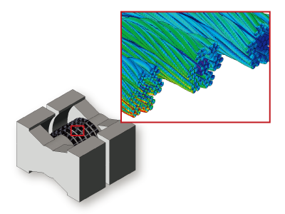
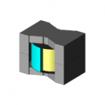
The Twist Effect of a Litz Wire
In this transformer example, a ferrite core was modeled with gap in order to keep flux density below 0.3T. Leakage flux will form around this gap and penetrate the coils in close proximity. This leakage flux induces losses that can be reduced by changing the winding to Litz wire. Using Litz wire reduces the copper losses by 20% by reducing the effects of the leakage flux.
Related materials
JMAG Users Conference Proceedings

Masakazu Akahane, HIOKI E.E. CORPORATION / Hiroyuki Sano, JSOL Corp....

Kazumasa Ide, Nagoya University...
White Papers

This paper describes an approach for modeling a wide-band impedance analysis using an electromagnetic finite element analysis that takes into account ...
This case study simulates high-frequency pathways accounting for parasitic components of each part via an equivalent circuit and evaluates the high-fr...
Application Catalog
In this example, we obtain the minute electromagnetic forces acting on a magnet that is moving translationally....
This case study explains modeling for frequency characteristics of impedance and loss using laminated and spiral-type chopper inductors....
A magnetic field analysis simulation based on the finite element method (FEM) can precisely evaluate the complex loss distributions of the coil and co...

