Contents
1. Introduction
2. Accuracy of motor plant model required for control calibration
3. Control calibration Example: Current Vector Calibration for Maximum Efficiency Control
3.1 Motor and Control Specifications
3.2 Plant model specifications
3.3 Calibration method of the current command value
3.4 Calibration result
3.5 Torque accuracy
3.6 Efficiency accuracy
4. Summary
5. References
1. Introduction
Control calibration is time-consuming work because it is carried out for every operating point using the actual machine. This paper examines realizing improved efficiency in control calibration by using a plant model. However, since control calibration is performed according to the characteristics of the actual machine, the plant model requires an accuracy equivalent to that of the actual machine. In this paper, the current command value of maximum efficiency control identified as an example of control calibration is examined and the accuracy required for the plant model is shown. It shows that accounting for iron loss including time harmonics is necessary to satisfy the required accuracy of torque and loss.
2. Accuracy of motor plant model required for control calibration
In control calibration, the gain and control command value are identified according to motor characteristics. Normally, control calibration was carried out using an actual machine for every motor and every operating point, which was time-consuming work. Here, the control calibration is performed using the plant model instead of the actual machine.
The accuracy of the plant model required for control calibration depends on the calibrated parameters. As an example, we look at the current command value when driving the motor with maximum efficiency control as an example. The accuracy of torque and loss is required in the plant model to make efficiency an objective function.
3. Control calibration Example: Current Vector Calibration for Maximum Efficiency Control
3.1 Motor and Control Specifications
Fig. 1 and Table 1 show the cross-section and specifications of the motor. Fig. 2 shows the control model. The current vector is controlled by the PI control. The current vector, which is the command value, is selected so that efficiency is maximized at each operating point by calibration.
3.2 Plant model specifications
Table 2 shows the resolution of the plant model. The calculation method of the iron loss is described as follows. When generating a plant model, a sine wave current is given to obtain the fundamental and spatial harmonic components. The time-harmonic iron loss is accounted for by using the iron loss equivalent resistor in the equivalent circuit in the control and circuit simulations. An FEA model and a plant model that doesn't account for iron loss were used as a reference to compare accuracy. Except for not accounting for iron loss, the latter has the same resolution.
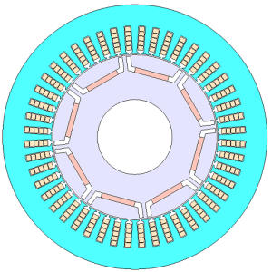 Fig. 1 Cross-section of the motor
Table 1 Motor specifications
| Number of poles/slots | 8/48 |
| Core material | 35JA300 |
| Magnet | NdFeB, Br=1.2(T) |
| Output | 80 (kW) |
| DC Voltage | 600 (V) |
| Maximum current | 250 (A) |
| Carrier Frequency | 6 (kHz) |
You need to sign in as a Regular JMAG Software User (paid user) or JMAG WEB MEMBER (free membership).
By registering as a JMAG WEB MEMBER, you can browse technical materials and other member-only contents for free.
If you are not registered, click the “Create an Account” button.
Create an Account Sign in


