Contents
- Introduction
- Accuracy required for ECU testing and plant models
- Motor Specifications
- Plant model specifications
- Torque control testing
- Response testing of speed control
- Testing of instantaneous interruption determination
- Summary
1. Introduction
ECU testing is performed under various conditions from the normal to the abnormal system. Furthermore, both the torque and rotation speed are tested in a wide region in the driving state of the motor. Normally, DQ models that do not account for spatial harmonics are often used in ECU testing. However, there is a risk that the accuracy of the plant model is insufficient causing incorrect testing when the design margin is reduced by miniaturization and high output of the motor, or when gain adjustment is performed aiming at high responsiveness. This white paper explains the accuracy of the plant model required for ECU testing and presents examples. This paper shows the need to account for voltage limitation in steady torque control, load step response in speed control, and account for the effect of spatial harmonics when determining instantaneous interruption.
2. Accuracy required for ECU testing and plant models
The accuracy required in the plant model for performing ECU testing is shown. Normally, the plant model used for control design is a model accounting for linear or magnetic saturation. These models are often used for ECU testing. This is because the motor and control are designed with a margin for required performance which can be applied to ECU testing even if the accuracy of the plant model is not high. However, due to the demand for miniaturization and high output of the motor, and higher control response, the requirements for the plant model also become more demanding when the margin of the design becomes smaller. Requirements differ according to testing content and the subject under control, and it becomes necessary to account for magnetic saturation, spatial harmonics, and loss. This paper shows that the model can be used for voltage limits in steady torque control, load step response in speed control, and determining instantaneous interruption.
3. Motor Specifications
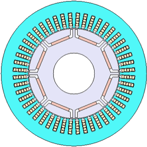
Fig. 1 and Table 1 show the cross-section and specifications of the motor. The same motor is used in the examples shown below.

Fig. 1 Cross-section of the motor
| Number of poles/slots | 8/48 |
| Core material | 35JA300 |
| Magnet | NdFeB, Br=1.2(T) |
| Output | 80 (kW) |
| DC Voltage | 600 V |
| Maximum current | 250 (A) |
| Carrier Frequency | 6 (kHz) |
4. Plant model specifications
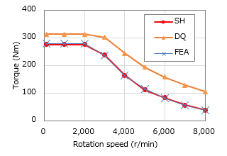
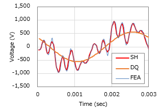
Two models are used to show the plant model accuracy required for ECU testing. One is a nonlinear DQ model (hereafter referred to as the DQ model) which is often used in control design, and the other is a model accounting for spatial harmonics (SH model), and the characteristics accounted for in the models are shown in Table 2. Table 3 shows the resolution of the models used in the example. The FEA model was used as a criterion for accuracy comparison.
| Magnetic saturation | Spatial resolution | |
| DQ model | Accounted (Note) | Not accounted |
| SH model | Accounted | Accounted |
(NOTE) Magnetic saturation of magnet flux is not taken into account.
 Fig. 2 NT Characteristics
 Fig. 3 Induced Voltage Waveform
You need to sign in as a Regular JMAG Software User (paid user) or JMAG WEB MEMBER (free membership).
By registering as a JMAG WEB MEMBER, you can browse technical materials and other member-only contents for free.
If you are not registered, click the “Create an Account” button.
Create an Account Sign in


