JMAG-Designer Ver.25.0 was released in February 2026.
JMAG continues to advance development toward the automation of design. To this end, Ver.25.0 brings further functionality enhancements. In particular, significant upgrades have been made to the automatic application of dimensional constraints, accelerated optimization calculations using surrogate models, and the motor design and evaluation features (JMAG-Express).
Here, we introduce some of the functional improvements and new features in Ver.25.0.
To perform dimensional optimization, it is necessary to apply dimensional constraints. With Ver.25.0, the scope of automatic constraints has been expanded to include stators of motors and more complex rotor shapes during detailed design phase. In addition, guidelines are provided for achieving full constraint when it is not automatically attained. Relatedly, the highlighting function for locations where dimensional constraints are applied has been improved. Furthermore, it is now possible to set design variables that are determined dependently, without applying dimensional constraints, as optimization constraints. For example, by setting a minimum width for the bridge area of an IPM motor, strength is maintained and the convergence of optimization calculations is improved.
In both offline and online optimization using surrogate models, the determination of whether a shape is valid—which previously took time—can now be performed by a surrogate model (Geometry Check Surrogate model), thereby speeding up optimization calculations. Optimization using surrogate models now also supports optimization of discrete values for dimensions and materials.
For addressing noise and vibration (NVH) from motors, analyzing excitation sources is important. With Ver.25.0, it is now possible to analyze the temporal and spatial order components of excitation sources using 2D Fourier Transform.
JMAG-Express has seen significant improvements in usability. For example, users can now customize the display of lists of design variables and response values to suit their preferences. Additionally, JMAG-Express will add evaluation items. It is possible to comprehensively evaluate relationships such as current phase, torque, and voltage, which are important motor characteristics. A thermal design scenario for axial flux motors has also been added.
Material modeling capabilities have been enhanced. It is now easier to define Halbach arrays for magnets. The number of divisions can also be set as a design variable for optimization. The calculation functions for superconductors continue to be strengthened. In Ver.25.0, it is now possible to define the angular dependence of the critical current density, enabling more realistic analysis.
Many other functional improvements and new features have been added as well. We encourage you to make full use of the new JMAG.
What is JMAG-Designer Ver.25.0 ?
INDEX
- Enhancements to the Automatic Constraint Function and Highlighting of Dimensional Constraints
- Constraints on dependent dimension parameters
- Introduction of Geometry Check Surrogate Models
- Acceleration of Optimization Calculations Using Geometry Check Surrogate Models
- Expanding the Scope of Application for Surrogate Model-Assist Optimization Calculations
- Provision of NVH Evaluation Method (2D Fourier Transform)
- Improvement of JMAG-Express Usability
- Display of Motor Characteristic Curves
- Permanent Magnet with Halbach Array
- Superconducting Analysis More Faithful to Actual Phenomena
1. Enhancements to the Automatic Constraint Function and Highlighting of Dimensional Constraints
Extension of applicable scope from conceptual design to detailed design.
 Examples of Detailed Shapes Now Automatically Constrained
Detailed design models may include more complex features such as notches on rotor surface, detailed flux barriers, divided magnets, stoppers, and ducts. With Ver.25.0, durability has been improved to ensure that even such complex shapes can achieve full constraint.
Identify quickly problem areas and solutions when automatic constraints fail.
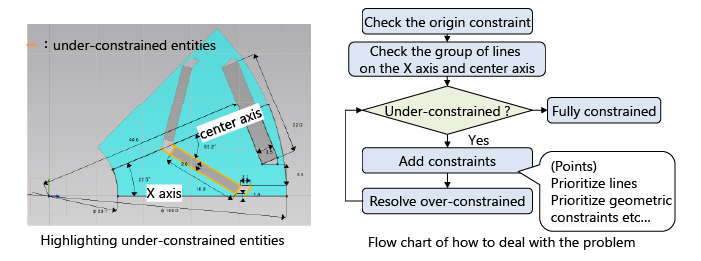 Highlighting of Under-Constrained Shapes and Flowchart for Solutions
In this rotor shape, it can be determined from the orange highlight that the area around the V-shaped magnet is not fully constrained. By following the flowchart and key steps, a fully constrained state can be achieved.
Visually confirm where each dimension parameter is defined.
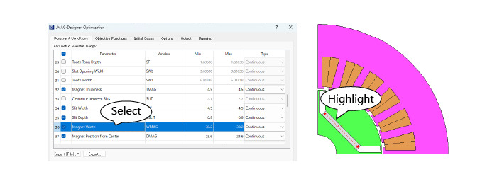 Dimension Parameter Highlighting Linked to the Optimization Setting Dialog
When a dimension parameter is selected in the optimization setting dialog, it is highlighted on the model view. Highlighting is available from the [Equations] dialog, the [Generate Parametric Cases] dialog and other dialogs also.
2. Constraints on dependent dimension parameters
It is possible to set constraint conditions on dimensions that are dependently determined by design variables.
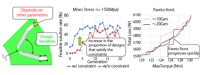 Optimization with the Minimum Width Constraint at the Outer Bridge
Even if the bridge width changes dependently on other dimension parameters, its minimum width can be constrained as measurement variable. By imposing a minimum width constraint, a large number of designs that satisfy the stress constraint are obtained, and the Pareto front progresses around the high-torque region in the same generations.
3. Introduction of Geometry Check Surrogate Models
In addition to the FEA surrogate model, Geometry Check Surrogate model has been introduced.
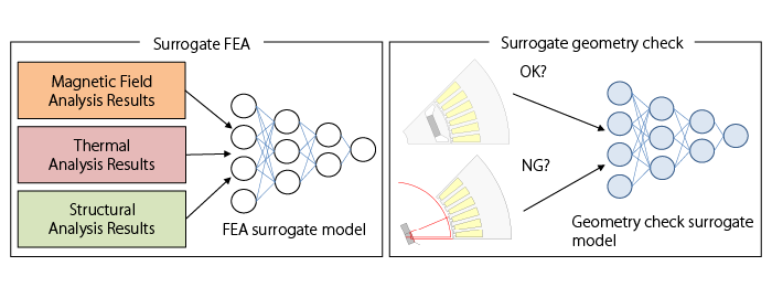 Design Exploration Using Surrogate Models
In optimization calculations using surrogate models, it was necessary to combine CAD-based shape verification with the FEA surrogate model. Replacing CAD-based shape verification with the surrogate model is expected to improve the performance of both offline and online optimization calculations.
4. Acceleration of Optimization Calculations Using Geometry Check Surrogate Models
Practical examples of speeding up online and offline optimization calculations using geometry check surrogate models.
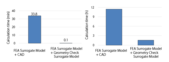 Comparison of Calculation Times with CAD-Based Methods (Left: Offline, Right: Online)
In the offline optimization example, optimization calculations with magnetic area constraints for an IPM motor can be executed in approximately 6 seconds. In the online optimization example In the online optimization example, by performing FEA every 10 generations achieved a 7-fold speedup compared to optimization calculations using CAD for shape verification (The optimization process is 2.5 times faster compared to optimization using only FEA) .
5. Expanding the Scope of Application for Surrogate Model-Assist Optimization Calculations
Complete optimization with discrete variables including materials within a practical timeframe.
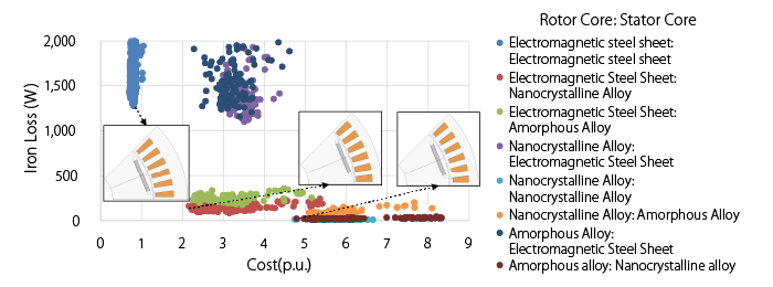 Optimization Calculation with Core Material and Geometric Dimensions as Design Variables
For nine material combinations created by varying the core materials of the rotor and stator across three types each, the trade-off between iron loss and material cost was evaluated in a single optimization calculation. Using low iron-loss materials (amorphous, nanocrystal) for the stator core resulted in a design with a smaller stator core size. Furthermore, by utilizing surrogate model-based optimization calculations, the optimization calculation time was reduced to half compared to optimization calculations using FEA alone.
6. Provision of NVH Evaluation Method (2D Fourier Transform)
Analyze the spatial and temporal components of magnetic and electromagnetic forces that cause vibration.
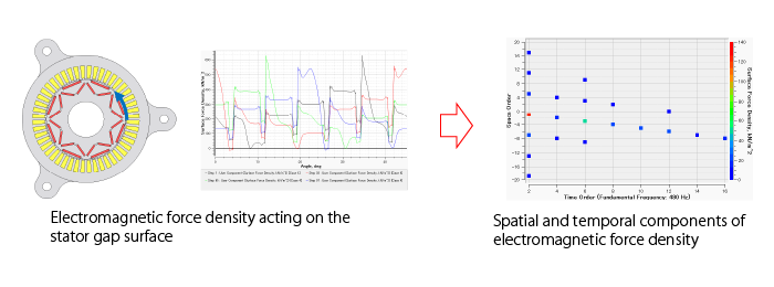 Analysis of Electromagnetic Force Components Acting on the Stator
To understand the components of electromagnetic vibration on the stator, the frequency and order of electromagnetic force density waves are displayed. These can be used to identify the components contributing to vibration. For example, in 8-pole, 48-slot motor, the time-frequency component (960 Hz) and spatial component (1 pole, 45 degrees, reverse phase) are dominant. Additionally, components caused by the number of slots can also be observed.
7. Improvement of JMAG-Express Usability
Customizable display of design variables and response values.
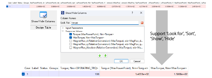 Customization of the List Display for Design Variables and Response Values
In this example, only the design variables and response values that include "Torque" in their names are displayed, improving visibility.
8. Display of Motor Characteristic Curves
Display characteristics desired by designers, such as current phase-torque.
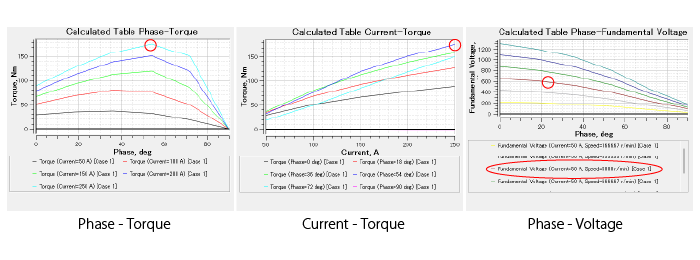 Motor Characteristics Added to the Machine Characteristics scenario
In addition to efficiency maps and NT curves, it is possible to evaluate phase-torque characteristics, current-torque characteristics, and phase-voltage characteristics. It is possible to determine that for this motor, torque is maximized around 54deg of phase rotation under high load, and that at 5,000 rpm, the maximum torque at a current of 250A is approximately 180 Nm, the voltage is 600V at 20deg of phase rotation.
9. Permanent Magnet with Halbach Array
Representing Halbach array through parameter settings.
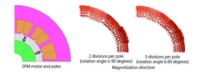 Example of SPM Motor with Halbach Array
Provides Halbach array for the magnetization patterns. This example shows the 2 cases of SMP motor. The number of poles is set to 8, and the number of divisions per pole to 2 and 3. The appropriate magnetization direction is obtained for each setting.
10. Superconducting Analysis More Faithful to Actual Phenomena
Supports the angular dependence of the critical current density of superconducting properties. Also enables the output of critical current density, allowing for analysis of the load state of superconductors.
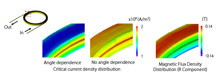 Superconducting Analysis Considering Angle Dependence
Superconducting analysis was performed on a double pancake coil. When considering angular dependence, the critical current density decreases near the coil ends. This occurs because the magnetic flux direction changes near the coil ends, leading to a decrease in critical current density.
The new functions and Features
For details, please see the following function introduction. (PDF, 3.10 MB: User authentication)
Introducing New Functions of JMAG-Designer Ver. 25.0
Documents
These are created using the functions in JMAG-Designer Ver.25.0 and later. Please feel free to use them.
Fast Global Exploration
- [JFT195] The Use of Custom Geometry in JMAG-Express Using Auto Constraint
- [JFT214] Optimization with Constraints on Dependent Dimension Parameters
- [JFT207] Offline Optimization Using a Surrogate Model
- [JFT213] Offline Optimization Using Response Value Surrogate Model and Geometry Check Surrogate Model
- [JAC319] Design Exploration of an IPM Motor Using an Offline Optimization
- [JAC317] Optimization via a Surrogate Model Using Materials as Design Variables
Multi-disciplinary Evaluation
- [JFT215] Two-Dimensional Fourier Transform for Section Graphs
- [JAC226] Vibration Characteristics Analysis of SPM Motors
Open to designers
- [JFT211] Parametric Analysis and Optimization in JMAG-Express Using Custom User Geometry
- [JAC304] Thermal Analysis of an Axial Flux Motor Accounting for Cooling
System Integration
Material
- [JAC314] Torque Analysis of an SPM Motor Using a Halbach Array
- [JAC315] Torque Analysis of an Axial Gap Motor Using a Halbach Array
- [JFT212] Hysteresis Curve Distortion Correction When Using Measured Results
- [JAC316] AC Loss Analysis of a CORC Cable
Module Download
The latest version of JMAG modules are available.
In addition, version information, release notes, manuals, etc. can be used. ( User authentication)
Update to LM-X license server 5.5.11 or later when using JMAG-Designer Version 24.0 or later.
Click here for more information on LM-X License Server Installer and License Update Manual ( User authentication)
Introducing JMAG-Designer Ver.17.0 – Ver.25.0
Articles about JMAG-Designer that have been released previously are available.- JMAG-Designer Ver.25.0
- JMAG-Designer Ver.24.0 / Ver.24.1 / Ver.24.2
- JMAG-Designer Ver.23.0 / Ver.23.1 / Ver.23.2
- JMAG-Designer Ver.22.0 / Ver.22.1 / Ver.22.2
- JMAG-Designer Ver.21.0 / Ver.21.1 / Ver.21.2
- JMAG-Designer Ver.20.0 / Ver.20.1 / Ver.20.2
- JMAG-Designer Ver.19.0 / Ver.19.1
- JMAG-Designer Ver.18.0 / Ver.18.1
- JMAG-Designer Ver.17.0 / Ver.17.1