In June 2020, JMAG-Designer Ver.19.1 has been released.
In JMAG-Designer Ver.19.1, the analysis parameter view and dashboard which was implemented in the previous version have been updated for easier use. While continuing to enhancement the solver and mesher the base of the FEA engines, we have also added and enhanced functions for optimization and the creation of efficiency maps.
Please enjoy taking full advantage of it.
What is JMAG-Designer Version 19.1 ?
 Analysis Parameter View
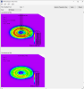 Dashboard
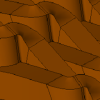 Coil Template
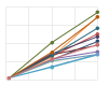 Parallel solver
 Periodicity of NGnet (Optimization : on/off method)
 Considering of PWM Losses
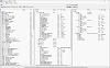
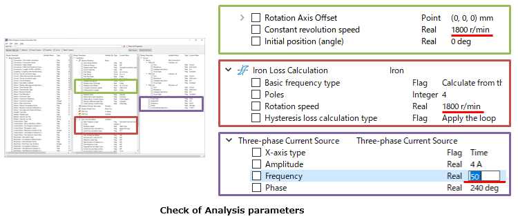 In the analysis parameter view, many parameters can be confirmed and modified in a few clicks. Here, an example of a motor is shown, and when changing the rotation speed, one can easy confirm in a single window that the rotation speed of the iron loss condition and the power supply frequency are matched to that change. The power supply frequency of 50 (Hz) is incorrect and can be corrected directly in that window.
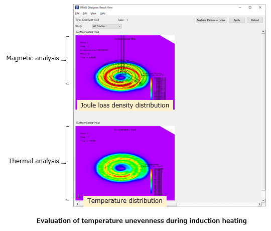 From Ver.19.1, it is possible to display the results of different studies side by side on the result view. In this example, the uniformity of the temperature distribution during induction heating is evaluated. Unevenness in temperature distribution can be observed, that thanks to the help of the Joule loss density distribution, can be linked to the shape of the heating coil.
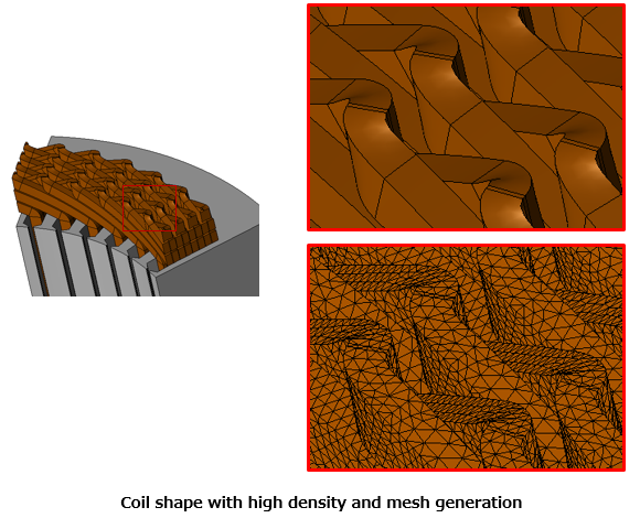 To reduce the winding space while avoiding contact between the coils, the shape will include many minute surfaces, curved surfaces and little space between them. A mesh that considers the skin depth is generated in the coil to accurately capture the eddy current distribution and evaluate AC losses.
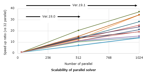 With the increase in model size and the number of cases, reducing the calculation time of those analysis has become a crucial requirement. In Ver.19.1, the number of cores that can be used in a parallel calculation was expanded from 512 to 1,024. Evaluating multiple large multi-million elements models resulted in a speed-up by up to 20 times in 512 parallels and up to 37 times in 1024 parallels, compared to 32 parallel.
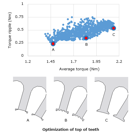 The calculation cost of topology optimization can be suppressed by including periodicity in the searched shapes. The examples shown are multi-objective optimizations, minimizing the torque ripple and maximizing the average torque. The tooth shapes of points A, B, and C on the Pareto are shown. The presence or absence of iron at the center of the teeth is a key parameter in the trade-off between torque ripple and average torque.
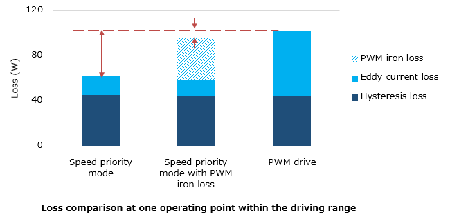 In the speed priority mode, the loss is calculated using a sine wave drive. As the effect of PWM is not taken into account the iron loss may be underestimated. In Ver.19.1, we introduced a method to estimate quickly the iron loss due to the PWM. The loss considering PWM iron loss in the speed priority mode is now close to the loss calculated when using a PWM drive without the need for a time-costly evaluation.
The new functions and Features
For details, please see the following function introduction. (PDF, 1.77MB: User authentication)
Introducing to new functions of JMAG-Designer Ver.19.1
Documents
These are created using the functions in JMAG-Designer Ver.19.1 and later. Please feel free to use them.
Solver
- [JFT111] Accounting for Arbitrary Motions
- [JAC225] Induced Voltage Analysis on Memory Motors Using Variable Magnets
Parametric / Optimization
- [JFT110] Evaluating the Effect of the Large Number of Holes Generated by Topology Optimization
- [JFT112] Defining Response Values with Scripts in Topology Optimization Using NGnet
- [JAC267] Topology Optimization of IPM Motor using Density Method
- [JAC268] SPM Motor Teeth Geometry Topology Optimization
Multi-physics
- [JAC205] Analyzing the Torque Characteristics of IPM Motors Using a Thermal Equivalent Circuit
- [JAC269] Vibration Analysis of a Motor Considering Shrink Fit Stress
Efficiency Map in JMAG-Designer
- [JFT109] Comparing Efficiency Maps and Loading External Data
- [JAC165] Creating IPM Motor Efficiency Maps
- [JAC264] Creating 6-Phase IPM Motor Efficiency Maps
- [JAC265] Creating Synchronous Reluctance Motor Efficiency Maps
Geometry
Pre / Post
Other
- [JAC230] 6-Phase SPM Motor Inverter Fault Simulation
- [JAC257] IPM Motor Topology Optimization
- [JAC271] Axial Gap Type Motor AC Copper Loss Analysis
- [JAC272] Thrust Analysis of Linear Actuator with a Curved Section
- [JAC273] Creating IPM Motor Efficiency Maps Accounting for AC Loss
Module Download
The latest version of JMAG modules are available.
In addition, version information, release notes, manuals, etc. can be used.
Video for Introducing the New Functions
A video complete with voice audio has been prepared to offer our users a better understanding of the new functions in JMAG-Designer Ver.19.1.
This is a lecture that can be attended via internet in your own time and for as many times as required.
Video for Introducing the New Functions of JMAG-Designer Ver.19.1
Introducing JMAG-Designer Ver.17.0 – Ver.25.0
Articles about JMAG-Designer that have been released previously are available.- JMAG-Designer Ver.25.0
- JMAG-Designer Ver.24.0 / Ver.24.1 / Ver.24.2
- JMAG-Designer Ver.23.0 / Ver.23.1 / Ver.23.2
- JMAG-Designer Ver.22.0 / Ver.22.1 / Ver.22.2
- JMAG-Designer Ver.21.0 / Ver.21.1 / Ver.21.2
- JMAG-Designer Ver.20.0 / Ver.20.1 / Ver.20.2
- JMAG-Designer Ver.19.0 / Ver.19.1
- JMAG-Designer Ver.18.0 / Ver.18.1
- JMAG-Designer Ver.17.0 / Ver.17.1

